Airbrakes & Apogee Control
A rocket cannot be told to stop climbing
Once the motor burns out, the vehicle coasts. Everything that decides how high it ends up — motor performance, mass, wind, air density — was fixed before it left the rail. Unless something can add drag on the way up.
That is what this division builds: a set of flaps that open into the airflow during coast, under onboard control, to trade excess energy for accuracy. It gives the vehicle a way to correct toward its target apogee instead of simply arriving wherever physics leaves it.
First integrated on Koeia, the 2026 vehicle
Where the system lives
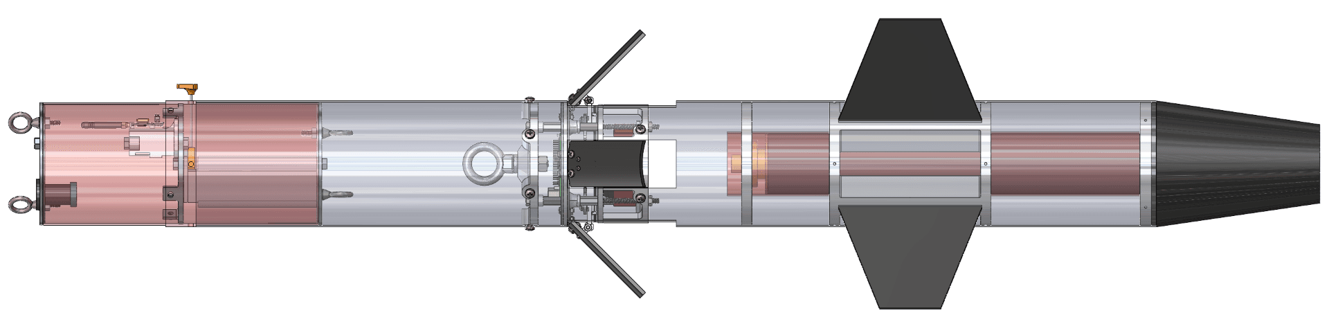
Airbrakes is not a bolt-on. The mechanism occupies a section of the airframe between the motor and the recovery bay, and every millimetre of that volume is shared with other divisions.
One actuator, symmetric deployment
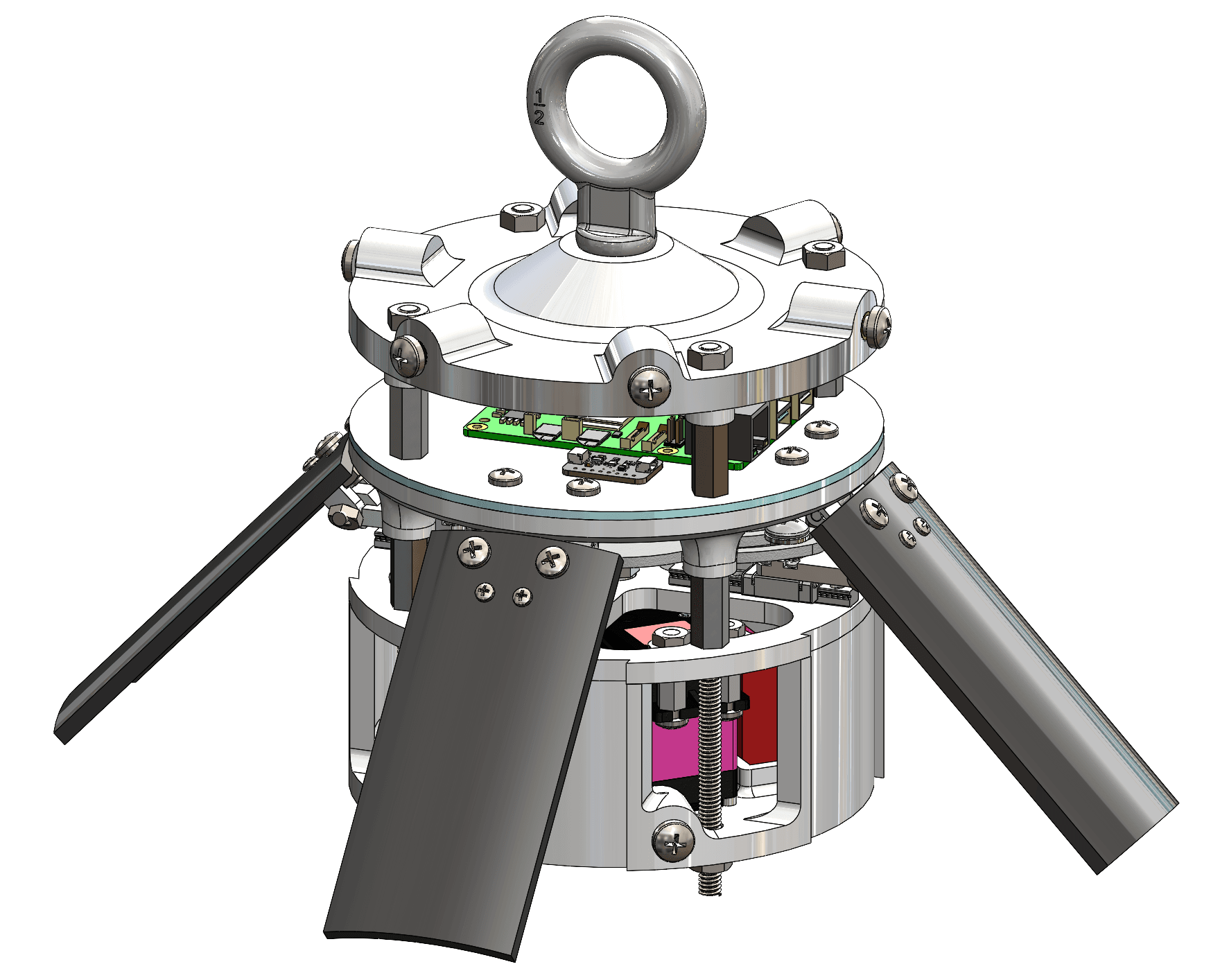
The flaps are linked so a single drive extends all of them together. That symmetry is not a convenience — asymmetric drag would push the vehicle off its heading, so the mechanism is designed to make uneven deployment mechanically difficult rather than merely unlikely.
The controller mounts directly to the module, so the sensing, the decision, and the hardware being commanded all travel as one assembly.
Sense → decide → actuate, onboard
During coast the system runs a closed loop with no human in it. Each stage below is a real part of the vehicle, not a diagram.
Know where you are, and how fast
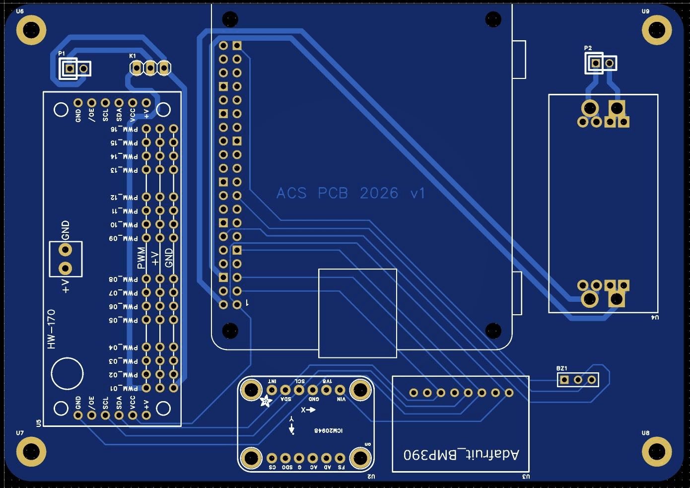
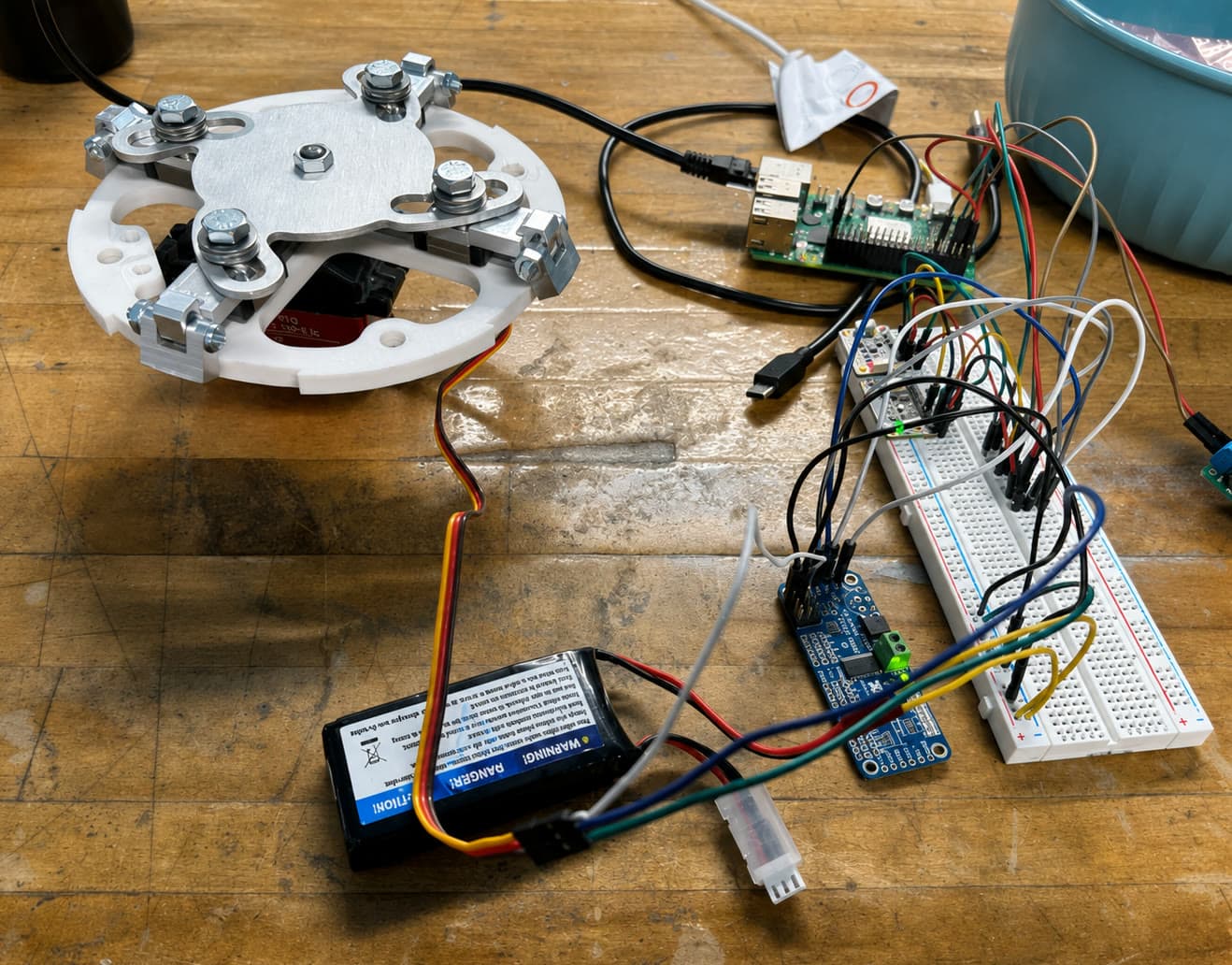
The onboard board carries a barometric pressure sensor and an inertial measurement unit, so the system can estimate altitude and motion continuously through the burn and coast phases.
Compare to the target, every cycle
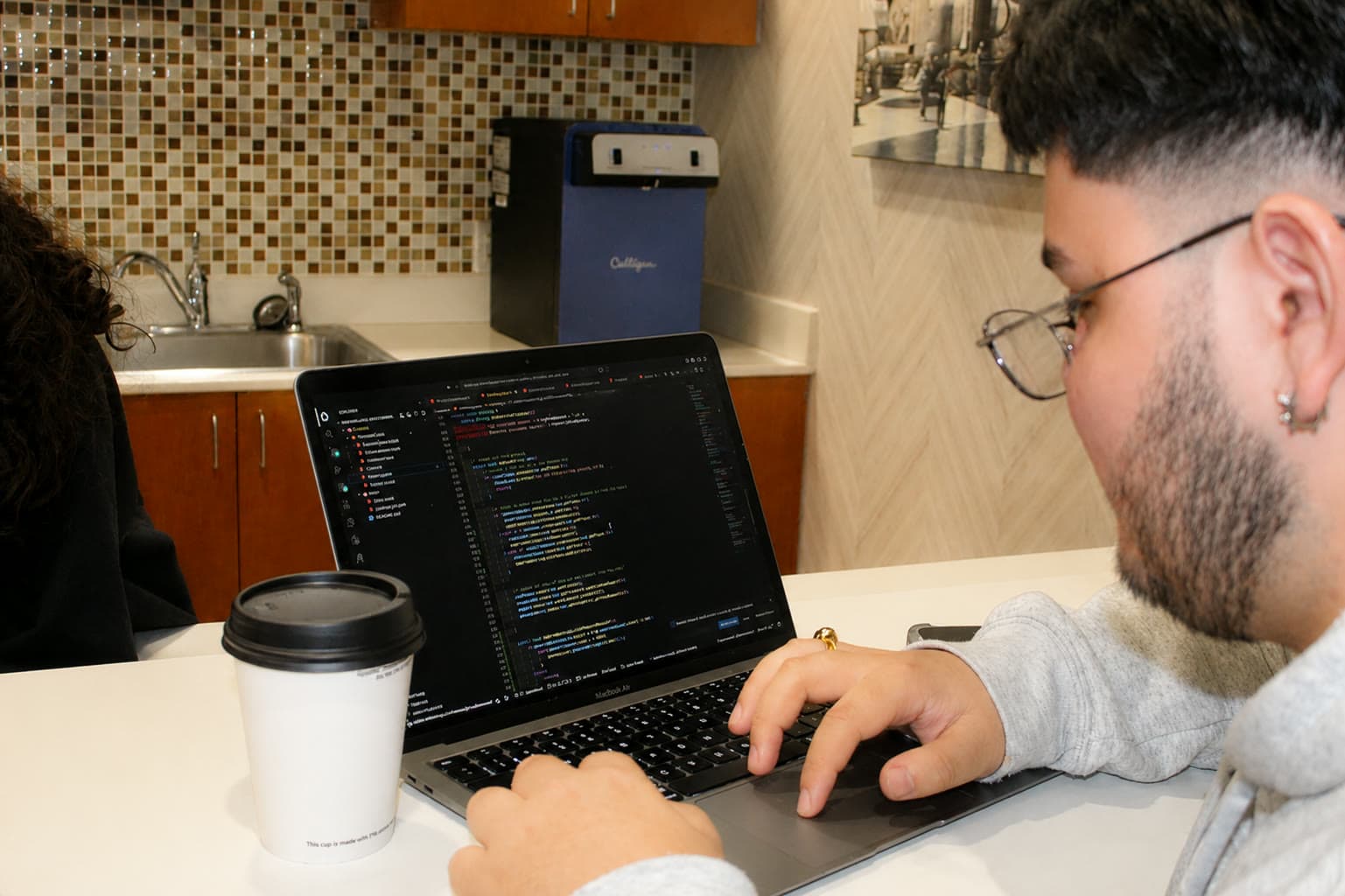
Onboard logic takes that state estimate, projects where the vehicle would coast to if it did nothing, and decides how far the flaps should be open right now. It runs unattended — there is no link to the ground during the seconds that matter.
Move the flaps, add the drag
A servo drives the linkage that pushes the flaps out into the airflow. More surface means more drag, which means less remaining altitude — the only control authority the vehicle has after the motor burns out.
Built here, validated together
Apogee control sits on the boundary between mechanism and aerodynamics, so the division's scope is drawn deliberately.
Airbrakes & Apogee Control owns
- The drag control mechanism and its structure
- Actuation and servo control
- Onboard control hardware and logic
- Sensors and software/hardware integration
- Bench and ground testing of the system
Flight Performance provides
- Computational fluid dynamics (CFD)
- RocketPy and Monte Carlo analysis
- Trajectory and apogee prediction
- Aerodynamic validation of the drag model
The two divisions work the same problem from opposite ends: one builds the thing that changes the drag, the other predicts what changing it will do.
What this division owns
Active drag control system & airbrake mechanism
The deployable surfaces themselves, and the linkage that drives them from a single actuator.
Actuation system & servo control
Sizing and commanding the actuator that has to move under aerodynamic load, repeatably.
Onboard control logic & hardware
The board, the firmware, and the decision loop that runs with no one watching.
Sensors & software/hardware integration
Making the electrical and mechanical halves behave as one system inside a body tube.
Testing, with Flight Performance for aerodynamic validation
Bench and ground testing here; simulation and aerodynamic validation in partnership with Flight Performance.
What members work with
- Control systems
- Servo actuation
- Embedded electronics & sensors
- Mechanical design
- Software/hardware integration
The bottom line
Airbrakes lets DRACO actively control its flight, closing the gap between predicted and achieved apogee — a defining capability for competitive performance, first integrated on the 2026 vehicle, Koeia.
/ Join Airbrakes
Control Is Something You Build
Mechanism design, embedded electronics, and control software in one division — with hardware that has to make its own decisions in flight, with no one able to intervene.